a. Description
 The engine is a dry sump type incorporating a separate oil tank which is mounted on the
right side of the frame. The oil in the tank is delivered under pressure by the oil pump
to lubricate the engine components. The oil accumulated in the crankcase sump is returned
to the oil tank by the scavenge pump, however, part of the oil is deverted to lubricate
transmission components.
 
1. Oil pump
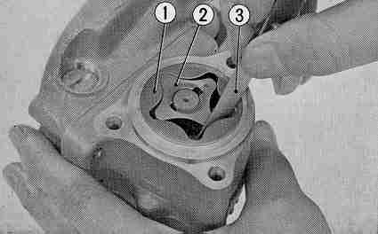
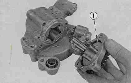
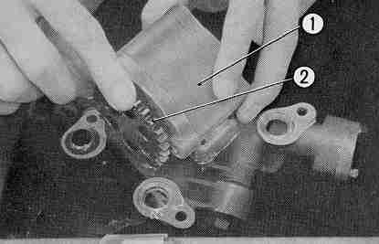
The oil pump is a rotor type trochoid pump mounted on the bottom of the crankcase and driven from the primary shaft through the kick gear. It consists of both the delivery and scavenge pumps, a leak stopper valve and a relief valve. (Fig. 3-4) (Oil leak stopper valve)
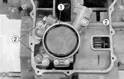
During engine operation, the oil pressure opens the oil leak stopper valve to maintain oil flow, and when the engine stops, the valve closes to prevent flow from the oil tank . (Fig. 3-5) (Relief valve)
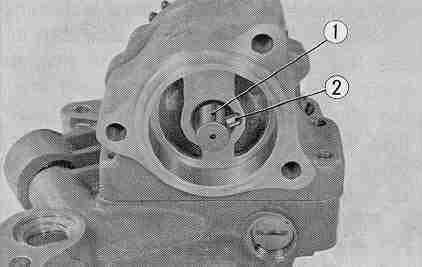
Relief valve is set at a specified pressure so that whenever the oil pressure exceeds this pressure, the valve opens and bypasses the oil to crankcase sump. In this way, the constant oil pressure is maintained.
This valve is incorporated in the delivery side of the oil pump. (Fig. 3-6)
Standard valve setting is 56.9lbs/in.2 (4.0+/-0.2 kg/cm2) at 4,000 rpm engine speed at oil temperature of 176'F (80'C).
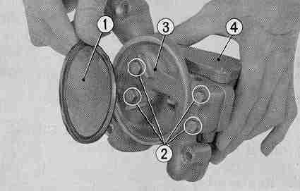
2. Oil filter
Oil filter is a full flow type using a replaceable element filter.
All the oil from the oil pump passes
 

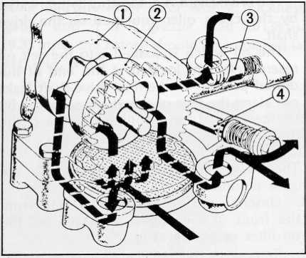
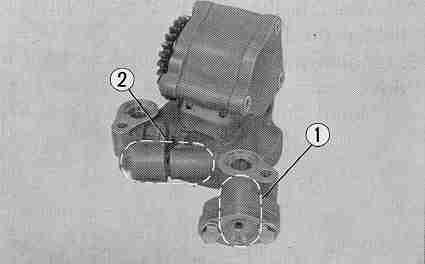
Fig. 3-4 (1) Delivery pump
         (2) Scavenge pump
         (3) Leak stopper valve
         (4) Relief valve


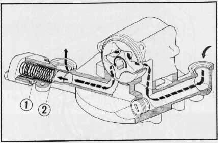
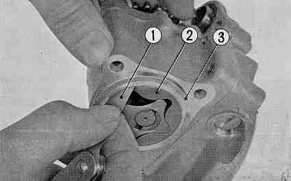
Fig. 3-5  (1) Oil leak stopper spring
          (2) Oil leak stopper valve


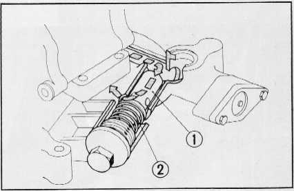
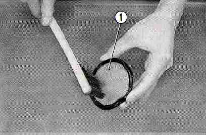
Fig. 3-6  (1)  Relief valve
          (2) Relief valve spring


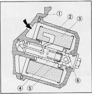
Fig. 3-7 (1) Crankcase   (4) By-pass valve spring
         (2) Oil filter case    (5)By-pass valve
         (3) Oil filter element (6)Center bolt


Fig. 3-8  (1)  By-pass valve sping
          (2) By-pass valve


Fig. 3-9 (1)  Oil filter center bolt
         (2) Oil filter case


Fig. 3-10  (1)  Oil pump
           (2) Oil pump mounting bolts

through the filter to be purified before being sent to the crankshaft. Filter assembly is mounted at the front of the engine with a bolt. Further, a by-pass valve is incorporated in the bolt to prevent oil stoppage when the element becomes clogged. (Fig. 3-7)
(By-pass valve)
When the element becomes clogged and the oil pump discharge pressure rises excessively, the by-pass valve open and the oil will by-pass the filter element and flow directly into the main gallery. At 21.3±2.8 lbs/in.2 (1.5 ± 0.2 k g/cm2) pressure difference, the valve is functioned. (Fig. 3-8)
3. Oil pressure warning lamp
The red oil pressure warning lamp is located to the left side of the tachometer on the gauge. Normally the light will be on when the engine is stopped and the main key switch is turned on. However, it will go off as soon as the engine is started and oil pressure reaches 7.1 Ibs/in2 (0.5 kg/cm2).
If the warning light came on while riding the engine should be stopped and the cause of the problem determined.
When operating the engine under extremely high oil temperature (over 244'F, 100'C), the warning light may intermittently come on at idling speed (800~900 rpm), however, this does not indicate a problem.
4. Drive chain lubrication
The drive chain is automatically lubricated by the chain oiler equipped on the drive shaft.
The oil which is soaked into the felt oil reserve element located at the end of the drilled passage in the final drive shaft leaks out along the face of the drive sprocket by the centrifugal force to lubricate the chain.
b. Disassembly
The oil pump can be removed with the engine mounted on the frame.
1. Unscrew the oil filter center bolt from the front of the engine and take out the oil filter case. (Fig. 3-9)
2. Remove the oil pan from the lower crankcase to get access to the oil pump.
3. Unscrew the three oil pump mounting bolts and remove the oil pump. (Fig. 3-10)

 
4. To remove the oil pump rotors, disassemble the side cover and remove the rotor A, (delivery side); next, remove the dowel pin and pull out the shaft from the rotor body. This will permit the rotor B (scavenge side) to be removed. (Fig. 3-11)
5. Remove the metal oil screen and unscrew the four bolts at the pump base to remove the oil pump body. (Fig. 3-12)
6. For disassembling the oil leak stopper valve, remove the oil leak stopper cap bolts. The oil leak stopper cap, spring and oil leak stopper valve can be removed from the oil pump. (Fig. 3-13)
7. For disassembling the relief valve, unscrew the relief spring cap, the relief valve spring and relief valve can be removed. (Fig. 3-13)

c. Inspection
1. Check the oil pump side cover for cracks.
2. Outer rotor and body clearance
Measure the clearance between the outer rotor and the body with a thickness gauge. If the clearance between rotor and body is greater than 0.0138 in. (0.35 mm), the rotor or the body should be replaced, depending on which part is worn. (Fig. 3-14)
3. Measuring the tip clearance
Measure the clearance between the outer rotor and the inner rotor with a thickness gauge and if it is greater than 0.0138 in. (0.35 mm), the rotors should be replaced in set. (Fig. 3-15)


Fig. 3-15(1) Outer rotor
        (2) Inner rotor
         (3) Thickness gauge


Fig. 3-11 (1) Oil pump rotor shaft
          (2) Dowel pin


Fig. 3-12 (1) Metal oil screen   (4) Oil pump base
          (2) 6mm hex bolts      (5)Oil pump body


Fig. 3-13 (1) Leak stopper valve
          (2) Relief valve


Fig. 3-14 (1) Thickness gauge
          (2) Pump body
          (3) Outer rotor


4. Measuring the leak stopper valve clearance Measure the body inside diameter and the leak stopper valve outside diameter using a dial gauge or a micrometer and if the clearance is calculated to be greater than 0.0067 in. (0.17 mm), the leak stopper valve or body whichever is worn beyond serviceable limit should be replaced.
5. Measuring the relief valve clearance
Measure the body inside diameter and the relief valve diameter using a dial gauge or a micrometer and if the clearance is greater than 0.0039 in. (0.1 mm), the body or the

Fig. 3-16 Oilstrainer
valve whichever is beyond serviceable limit should be replaced.
6. Measuring the rotor thickness and the body clearance
Measure the rotor thickness with a micrometer and the depth using the depth micrometer and if the clearance is greater than 0.0047 in. (0.12 mm), the parts should be repaired or replaced.
7. Cleaning oil strainer
Wash the oil strainer in clean solvent. Be sure to replace the oil strainer with a new one if damaged. (Fig. 3-16)

Fig. 3-16 Oil strainer
d. Reassembly
1. Assemble the oil pump component parts in accordance with Fig. 3-17. Assemble the relief valve, relief valve spring and screw the relief spring cap securely.
2. Assemble the oil leak stopper valve, spring, 0 ring and oil leak stopper cap, and then tighten 'the two bolts.
3. Mount the inner and outer rotors B into the oil pump body, and insert the oil pump drive gear. Do not forget to install the rotor dowel pin.
4. Mount the inner and outer rotors A into the pump body.


Fig 3-17
(1) Oil pump drive gear
(2) 4x14.8mrn pin
(3) Oil pump right cover
(4) 46x2 ''O" ring
(5) 4x8 dowel pin
(6) Inner rotor B
(7) Outer rotor B
(8) "O" ring collar
(9) 15x2.5 "O" ring
(10) Oil pump gasket
(11) Oil pump body
(12) 11x15x3 Oil seal
(13) Outer rotor A
(14) Inner rotor A
(15) Oil pump left cover
(16) 6x59 flat screw
(17) 6 mm flat washer
(18) 6x32 hex bolt
(19) Relief spring cap
(20) Relief valve spring
(21) Relief valve
(22) Oil pump base
(23) Oil strainer screen
(24) Oil leak stopper seal
(25) Oil leak stopper valve
(26) Oil leak stopper spring
(27) 15x2.5 "0" ring
(28) Oil leak stopper cap
(29) 6mm flat washer


Fig 3-18 (1) "O" ring


Fig 3-19 (1) Oil pump assambly
         (2) Oil pump drive gear
 

Note: Do not forget to install the 0-ring on the side cover. (Fig. 3-18)
5. After completing the assembly of the rotor, turn the shaft by hand to assure that it is turning smoothly.


6. Immerse the pump in oil and turn the pump until filled with oil before reinstalling the pump on the crankcase. (Fig. 3-19)
7. When reinstalling the oil pump on the crankcase, do not forget to install the oil guide pins (3 each) and the 0-ring (3 each).
8. Changing oil and filter element procedures should be referred to group 19 on page 170.